A pin header is one of the simplest and most widely used connectors in electronic equipment. It consists of a row or multiple rows of metal pins held in an insulating plastic housing. Pin headers are commonly mounted on printed circuit boards (PCBs) to provide electrical and mechanical connections between boards, wires, and other components.
Because of their simple structure, flexible configurations, and relatively low cost, pin headers are widely used in industrial equipment, control systems, consumer electronics, development boards, and many other applications.
A pin header, also called a male header or pin header connector, is a connector with exposed metal pins arranged in a defined pattern.
The pins are normally made from copper alloys and held in an insulating housing. Depending on the application, the pins can be supplied in different lengths, shapes, rows, pitches, and mounting configurations.
A typical pin header includes three basic parts:
Metal contacts – provide the electrical connection.
Insulator housing – maintains the position and spacing of the contacts.
Mounting section – allows the header to be installed on or through a PCB.
Pin headers can be supplied as standard components or customized according to a customer's drawing and application requirements.
A pin header provides a fixed array of electrical contacts between a PCB and another component or connector.
For example, a pin header mounted on one PCB can mate with a female header mounted on another PCB. The male pins enter the female contacts, creating multiple electrical connections at the same time.
Depending on the design, a pin header can also be used with wires, sockets, or other mating components.
The simple structure makes pin headers particularly useful when a reliable, compact, and easy-to-assemble connection is required.
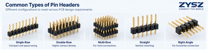
Pin headers can be classified by their number of rows, pin orientation, and mounting method.
A single-row pin header has one line of contacts. It is commonly used where PCB space is limited or where a simple connection is required.
A double-row pin header has two parallel rows of contacts. It provides a higher contact density without significantly increasing the PCB footprint.
For applications requiring a larger number of electrical connections, three or more rows can be used. The exact configuration depends on the PCB layout and electrical requirements.
In a straight pin header, the contacts extend vertically from the PCB. This is one of the most common configurations for board-to-board and PCB connection applications.
A right-angle pin header has contacts bent at 90 degrees. It is useful when the mating connector or cable needs to run horizontally along the PCB.
The choice between straight and right-angle versions depends mainly on PCB layout, available space, and the required mating direction.
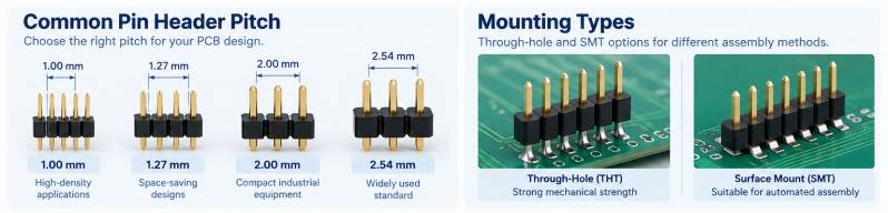
Pitch is the center-to-center distance between adjacent pins. It is one of the most important dimensions when selecting a pin header.
Common pin header pitches include:
Pitch
Typical Characteristics
1.00 mm | Compact, high-density applications |
1.27 mm | Space-saving PCB designs |
2.00 mm | Compact industrial and electronic equipment |
2.54 mm | Widely used standard configuration |
Smaller pitch allows more contacts to be placed in a limited area, while larger pitch generally provides more space between contacts and can simplify assembly and mating.
The selected pitch must match the PCB layout and the corresponding mating connector.
Pin headers are commonly available in through-hole and surface-mount (SMT) configurations.
Through-hole pin headers have terminals that pass through holes in the PCB and are soldered on the opposite side.
They are widely used where mechanical strength and secure PCB mounting are important.
SMT pin headers are mounted directly onto the surface of the PCB without requiring through-holes.
They are suitable for automated PCB assembly and compact electronic designs.
The choice between through-hole and SMT depends on the PCB design, assembly process, mechanical requirements, and production method.
When selecting or designing a pin header, several specifications should be considered.
Number of Positions
Defines how many individual contacts are included in the connector.
Number of Rows
Determines whether the connector is single-row, double-row, or multi-row.
Pitch
Defines the spacing between adjacent contacts and must match the PCB and mating connector.
Pin Length
Pin length can affect PCB mounting, mating depth, and the available connection area.
Pin Shape
Common configurations include straight and right-angle contacts. Different terminal shapes can be designed for specific assembly requirements.
Mounting Type
The connector may use through-hole or SMT mounting depending on the PCB assembly process.
Insulator Material
The housing material should be selected according to operating temperature, mechanical requirements, and application environment.
Contact Material
Copper alloys such as brass or phosphor bronze may be used depending on the required electrical and mechanical performance.

Pin headers are used in a wide range of electronic and industrial applications.
Common examples include:
PCB-to-PCB connections
Board-to-board connectors
Wire-to-board connections
Industrial control equipment
Automation equipment
Power and signal connections
Development and evaluation boards
Consumer electronics
Embedded electronic systems
Their simple design also makes them suitable for customized electronic assemblies where standard connectors may not meet specific dimensional requirements.
The correct pin header should be selected according to both electrical and mechanical requirements.
Before selecting a connector, check:
Pitch – Does it match the PCB layout?
Number of positions – How many circuits are required?
Rows – Is a single-row or multi-row configuration needed?
Mounting method – Through-hole or SMT?
Pin orientation – Straight or right-angle?
Pin length – Is sufficient length available for mounting and mating?
Material and operating temperature – Are they suitable for the application?
Mating connector – Does the pin header match the required female connector or socket?
For custom applications, the connector drawing and dimensional requirements should be reviewed before production.
Standard pin headers are available in many combinations of pitch, positions, rows, pin length, and mounting styles. They are suitable for many general-purpose applications.
However, some projects require special dimensions or configurations, such as:
Non-standard pin length
Custom pin spacing
Special contact shape
Customized housing dimensions
Special plating requirements
Custom packaging
In these cases, a connector manufacturer can develop or modify the design according to the customer's drawing and technical requirements.
ZYSZ Industry supports custom pin header development, including stamping, molding, plating, assembly, and inspection.
Pin headers are simple but highly versatile connectors used throughout the electronics industry. Their flexible configurations allow engineers to select different pitches, rows, pin lengths, mounting methods, and orientations according to the application.
For standard projects, an existing pin header configuration may be sufficient. For specialized applications, a customized design can provide a better fit for the PCB and assembly requirements.
When choosing a pin header, the most important factors are pitch, positions, rows, mounting method, pin orientation, dimensions, materials, and mating requirements.
For custom requirements, providing a drawing or detailed specification is the best way to determine the right connector design.
Pin headers are mainly used to provide electrical connections between PCBs, wires, and other electronic components or connectors.
A pin header has exposed male contacts, while a female header contains socket contacts designed to receive the pins.
2.54 mm is one of the most widely used pin header pitches, while 2.00 mm, 1.27 mm, and 1.00 mm are commonly used for more compact designs.
Yes. Pin headers can be customized in areas such as pitch, number of positions, pin length, contact shape, housing dimensions, plating, and packaging.
Contact: Steven
Phone: +86 18026591840
E-mail: biz@zyszindustry.com
Whatsapp:+86 13798308364
Add: B601/608, Building 4,Mingrenju Industrial Park,Shatian, Kengzi,Pingshan,Shenzhen, Guangdong, 518122